


 English
How to Use Wire Rope Aluminum Sleeves: Sizing, Swaging & Installation Guide
Content
- 1 An Aluminum Sleeve Only Works If the Swage Is Right
- 2 Match the Sleeve to the Rope Before You Touch a Press
- 3 Step-by-Step: Making a Correct Swage Termination
- 4 Choosing the Right Tool and Applying Correct Pressure
- 5 Common Mistakes That Undermine Holding Strength
- 6 Inspecting the Finished Termination
- 7 When Aluminum Is — and Isn't — the Right Choice
An Aluminum Sleeve Only Works If the Swage Is Right
A wire rope aluminum sleeve does not grip a rope the way a knot or a clip does. When the sleeve is compressed by a swaging tool, the aluminum flows around the wire strands and cold-welds into the surface irregularities of the rope, forming a solid mechanical bond rather than a simple pinch point. Get the compression wrong — undersized sleeve, wrong die, missing pass — and that bond never forms properly, no matter how strong the sleeve looks on the outside. This is why installation procedure matters as much as sleeve selection. General Metals has spent two decades supplying rigging hardware into lifting, marine, and industrial markets, and the single most common cause of field failures we hear about is not a defective sleeve — it's an installation shortcut.
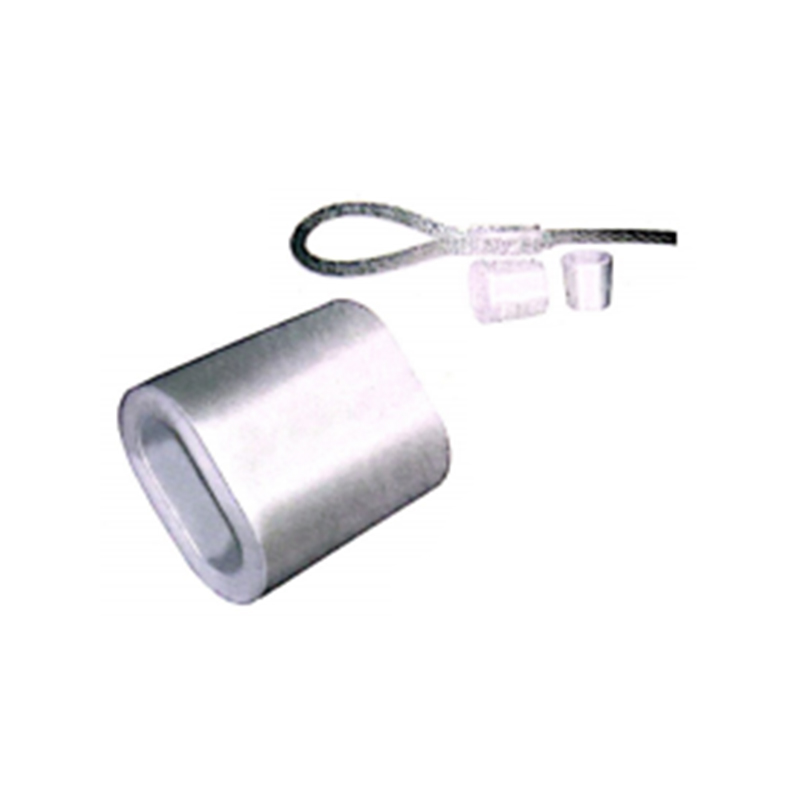
Match the Sleeve to the Rope Before You Touch a Press
Every aluminum sleeve is sized to a specific rope diameter range, and there is very little tolerance for guessing. A sleeve that is too large for the rope will not compress down far enough to displace the aluminum into the strand gaps, leaving voids that reduce holding strength. A sleeve that is too small will not seat the rope evenly, causing the swage to crush one side before the other.
Before ordering, confirm:
- Exact rope diameter, measured across the crown of the strands, not the valleys
- Rope construction — 7x7 and 7x19 ropes seat differently inside the same nominal sleeve bore
- Working load requirement, since sleeve wall thickness and length both scale with rated capacity
- Loop style — Nicopress-style single sleeves versus stop sleeves used for shock-cord and control-cable terminations
A rough guide for common rope-to-sleeve pairings looks like this:
| Rope diameter | Typical sleeve type | Recommended press passes |
|---|---|---|
| 1/16" – 3/32" | Single-barrel oval | 1–2 |
| 1/8" – 3/16" | Double-barrel or stop sleeve | 2–3 |
| 1/4" and above | Heavy-duty oval, multi-groove | 3–4 |
Step-by-Step: Making a Correct Swage Termination
The process is mechanically simple, but each step has a failure point if rushed.
- Cut the rope end clean and square, then seize or tape it to prevent the strands from unlaying before the sleeve goes on.
- Thread the sleeve onto the rope, form the loop around a thimble if the application calls for one, and feed the running end back through the sleeve.
- Position the sleeve so the dead end extends slightly past the sleeve mouth — a common defect is a tail that is too short to hold once the sleeve compresses.
- Set the sleeve into the correctly sized die. Using an oversized die is one of the most frequent installation errors, because it under-compresses the aluminum and leaves the swage visually acceptable but mechanically weak.
- Make the first press at the throat of the sleeve, nearest the loop or thimble, then work outward toward the tail in sequential passes, slightly overlapping each compression.
- Check that the sleeve has flattened evenly on both barrels with no visible cracking, and that the finished dimension matches the swage chart tolerance for that sleeve size.
For high-cycle or safety-critical assemblies, many installers prefer factory-terminated options instead of field swaging altogether. GMC's wire rope aluminum sleeves are supplied with matched swage specifications so the press setup is predictable rather than estimated on site.
Choosing the Right Tool and Applying Correct Pressure
Hand-crimping tools work for light-duty and hobbyist applications up to roughly 3/16 inch rope, but anything used for load-bearing rigging should be compressed with a hydraulic or mechanical swaging press matched to the sleeve manufacturer's die chart. Under-pressing is far more common than over-pressing, because an under-swaged sleeve still looks finished. The only reliable way to confirm correct compression is to measure the swaged dimension with calipers against the published tolerance, not to judge it by eye.
A few points worth building into a standard shop procedure:
- Keep dies matched to sleeve size — mixing die sets between suppliers introduces tolerance drift
- Recalibrate hydraulic presses periodically, since pressure loss reduces swage depth without any visible symptom
- Log the die number and press pressure used on safety-critical assemblies for traceability
Common Mistakes That Undermine Holding Strength
Field failures in aluminum sleeve terminations trace back to a short, repeatable list of causes:
- Using a copper-rated die on an aluminum sleeve, since the two materials compress at different rates and require different tooling
- Skipping a press pass to save time, leaving one section of the sleeve loose
- Leaving too short a tail, so the running end pulls free under load even though the sleeve itself held
- Reusing a sleeve after a failed swage attempt, which introduces micro-cracks that weaken the second compression
- Pairing an aluminum sleeve with a rope diameter outside its rated range, which was the single biggest driver of undersized swage failures we've traced in warranty inquiries
None of these are exotic problems — they are procedural gaps that a documented installation checklist eliminates almost entirely.
Inspecting the Finished Termination
Before a swaged assembly goes into service, it should pass a short visual and dimensional check:
- No visible cracks, splits, or sharp edges on the sleeve body
- Sleeve length and flat dimension within the manufacturer's published swage tolerance
- Rope strands not cut, pinched, or protruding through the aluminum
- Tail length sufficient to prevent slip under proof load
For rigging used in lifting or safety applications, a proof-load test on a sample termination from each production batch is standard practice, and many buyers request mill or batch certification alongside the hardware itself. GMC's factory testing covers tensile, fatigue, and salt-spray verification across its rigging hardware lines, and full details on the broader wire rope accessories range — including steel and copper sleeve alternatives for different corrosion and conductivity needs — are available for buyers comparing termination methods before specifying a project.
When Aluminum Is — and Isn't — the Right Choice
Aluminum sleeves are the standard choice where light weight, non-magnetic properties, and cost efficiency matter, which is why they dominate control cables, fall-protection lanyards, fencing, and light rigging assemblies. In marine or high-corrosion environments, however, aluminum's galvanic behavior against stainless rope can be a limiting factor, and copper or stainless sleeves are often specified instead. Matching sleeve material to both the rope alloy and the service environment is as important as getting the swage dimensions right — a technically correct swage on the wrong material pairing still shortens service life.
Related Products
-
 View More
-
 View More
ASTM A1023 Galvanized 7X7 7X19 Small Diameter Flexible Specialty Wire Rope
-
 View More
8×36 Steel Wire Rope ISO 2408 Class – Ultra-Flexible 8-Strand Rope
-
View More
35(W)×7+FC Steel Wire Rope – EN 12385-4
-
View More
6×7 Steel Wire Rope ISO 2408 Class – High Tensile Strength Galvanized Wire Rope
-
View More
6×19M Steel Wire Rope ISO 2408 Class – Flexible & Durable Wire Rope
Contact Us
-

-
 +86-13395162883 / +86-0510-86361180
 -
 No. 25 Xizhang Road, Changshou Village, Zhouzhuang Town, Jiangyin City, Wuxi City, Jiangsu Province, China


- Quick Links
- Product Categories
- Wire Rope
- Wire Rope Fittings
- Chain
- Wire Rope Accessories
- Packaging Types

Message Us Now !
