


 English
Wire Rope Aluminum Sleeves: Swage Strength, Sizing & Failure Modes
Content
- 1 An Aluminum Sleeve Creates a Cold-Welded Mechanical Bond, Not Just a Pinch Point
- 2 Oval Sleeve and Stop Sleeve: Two Different Components for Different Functions
- 3 Sizing Protocol and the Consequence of a Mismatch
- 4 Swaging Tool Requirements and the Hand Tool vs. Hydraulic Decision
- 5 The Double-Sleeve Standard for Lifting Applications
- 6 Corrosion Considerations and Aluminum-Steel Galvanic Compatibility
- 7 Common Failure Modes and Field Identification
- 8 Stainless Steel Wire Rope and the Special Case for Aluminum Sleeves
- 9 Alternative Sleeve Materials and the Copper and Zinc Options
- 10 The Role of the Thimble in Protecting Both Sleeve and Rope
An Aluminum Sleeve Creates a Cold-Welded Mechanical Bond, Not Just a Pinch Point
A wire rope aluminum sleeve, properly known as a swage sleeve or ferrule, functions as a termination fitting that permanently secures the end of a wire rope into an eye or splice. When compressed with the correct swaging tool, the ductile aluminum material deforms plastically around the individual wire strands, flowing into the valleys between them and creating a cold-formed mechanical interlock that distributes the tensile load evenly across every strand in the rope cross-section. A correctly swaged sleeve on galvanized or stainless steel wire rope using an oval aluminum sleeve achieves a holding strength of 85% to 90% of the wire rope's minimum breaking strength when the sleeve length, before-swage inside diameter, and after-swage compression specification are all met. The aluminum alloy used—typically 5052 or 6061 in wrought form or A380 in cast form—is selected for its combination of ductility during compression, corrosion compatibility with the wire rope material, and work-hardening behavior that increases the sleeve's post-swage strength to resist the hoop stress exerted by the loaded rope strands attempting to pull free.
Oval Sleeve and Stop Sleeve: Two Different Components for Different Functions
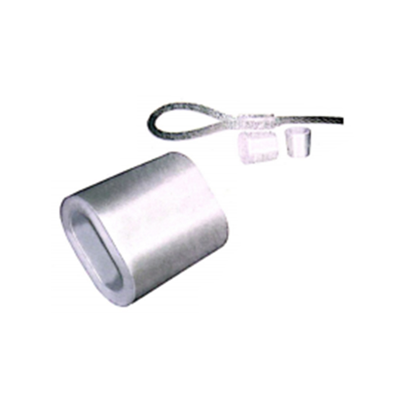
The term wire rope aluminum sleeve encompasses two functionally distinct hardware types that are frequently confused. An oval sleeve, also called a Flemish eye sleeve, has an elongated oval profile with two parallel internal bores that accept both legs of a wire rope loop. It is swaged across its width, compressing both bores simultaneously, and is the primary load-bearing termination for creating a permanent eye at the end of a wire rope. A stop sleeve, by contrast, is a short cylindrical aluminum tube with a single through-hole, swaged directly onto a single wire rope leg to create a mechanical stop—such as the retainer that prevents a wire rope from pulling through a pulley block or the stop that secures the tail of a wire rope after it passes through an oval sleeve. Confusing the two and using a stop sleeve where an oval sleeve is required for load-bearing termination will result in a connection that fails at less than 40% of the rope's breaking strength because the stop sleeve engages only one leg and lacks the balanced load distribution of the dual-bore oval design.
Sizing Protocol and the Consequence of a Mismatch
An aluminum sleeve is sized to a specific wire rope diameter with an extremely narrow tolerance window. The before-swage inside diameter of the sleeve bore must be 0.2 to 0.5 millimeters larger than the nominal rope diameter to allow the rope to pass through without jamming while leaving minimal void space that the aluminum must fill during compression. A sleeve that is one size too large will not compress sufficiently onto the rope strands; the aluminum will reach its compression limit before it has flowed fully into the strand interstices, leaving internal voids that act as stress concentration points and reduce holding strength by up to 30%. A sleeve that is one size too small cannot be threaded onto the rope without strand damage, and forcing it causes individual outer wires to displace and kink, creating a weakened cross-section at the exact point where the termination applies its highest stress. Sleeve sizing charts published by manufacturers match each rope diameter to a specific sleeve part number, and the sizing is specific to the rope construction—a 6x19 fiber-core rope and a 7x19 independent-wire-rope-core rope of the same nominal diameter may require different sleeve specifications because the actual outside diameters differ slightly due to the different strand packing geometries.
Before-Swage Inspection and the Tail Length Rule
Before compression, the wire rope tail protruding from the sleeve must be long enough to allow visual verification that the rope did not slip during swaging. The standard rule is a minimum tail length equal to one sleeve length for oval sleeves and two rope diameters for stop sleeves. After swaging, if the tail has retracted into the sleeve, the rope slipped during compression and the termination must be cut off and remade. The tail also provides the material for a secondary safety measure: on critical lifting applications, the tail is often served with wire or fitted with an additional stop sleeve as a backup retainer.
Swaging Tool Requirements and the Hand Tool vs. Hydraulic Decision
The compression of a wire rope aluminum sleeve requires a swaging tool that applies controlled, parallel-sided compression to a specified after-swage dimension. A hardware-store bolt cutter or a hammer and punch cannot produce a safe swage. The minimum acceptable tool for oval sleeves on wire rope up to 5 millimeters in diameter is a manual swaging tool with hardened steel jaws machined to the correct post-compression profile. These tools are compound-leverage designs that multiply hand force into several tons of compression pressure at the jaw faces. For rope diameters above 5 millimeters, a hydraulic swaging press with interchangeable dies is required to generate the consistent 8 to 15 tons of force needed to fully compress the aluminum sleeve into the rope structure. The critical quality indicator for any swaging tool is its ability to produce a repeatable after-swage dimension—typically specified as a gauge measurement across the compressed sleeve at its widest point—and a tool whose jaws are worn, sprung, or mismatched to the sleeve size will produce an under-compressed sleeve that appears visually acceptable but fails below the rated load.
The Go/No-Go Gauge and After-Swage Verification
After compression, the swaged sleeve must be checked with a go/no-go gauge supplied by the sleeve manufacturer or specified on the manufacturer's data sheet. The gauge verifies that the compressed width of the sleeve falls within the acceptable range—typically plus 0.2 millimeters and minus 0.1 millimeters from the nominal after-swage dimension. A sleeve that measures oversize on the gauge has been under-compressed and will not develop full holding strength. A sleeve that measures undersize has been over-compressed, which can crack the aluminum or crush the internal wire rope strands, creating a failure initiation point. The gauge check is not optional for any lifting, rigging, or safety-critical application; it is the only objective verification that the swage was performed correctly.
The Double-Sleeve Standard for Lifting Applications
Industry standards for wire rope slings and lifting assemblies, including ASME B30.9 and EN 13411-3, require that a Flemish eye splice terminated with aluminum oval sleeves use a minimum of one sleeve for wire rope diameters up to 6 millimeters, two sleeves for diameters from 6 to 12 millimeters, and three sleeves for diameters above 12 millimeters. The sleeves are spaced evenly along the tail, with the first sleeve positioned as close to the eye throat as practical and subsequent sleeves at intervals of approximately one sleeve length. The multiple-sleeve requirement is not redundancy for its own sake; it addresses the fact that a single sleeve concentrates the entire tensile load at one point, and if that sleeve is compromised—by a manufacturing defect, corrosion, or an off-spec swage—the entire termination fails without warning. Multiple sleeves distribute the load and provide progressive failure indication: if the first sleeve begins to slip, the load transfers to the second sleeve, and the tail protrusion from the first sleeve will visibly change, alerting an inspector to the developing failure during a routine examination.
Corrosion Considerations and Aluminum-Steel Galvanic Compatibility
An aluminum sleeve in contact with steel wire rope creates a galvanic couple in the presence of an electrolyte, such as rainwater, salt spray, or industrial atmospheric moisture. Aluminum is anodic to steel on the galvanic series, meaning the aluminum sleeve will preferentially corrode to protect the steel wire rope. In dry indoor applications, this galvanic effect is negligible and the sleeve will outlast the rope. In marine environments, coastal outdoor installations, or chemical processing facilities, the galvanic corrosion rate accelerates dramatically. The mitigation for these environments includes selecting anodized aluminum sleeves with a minimum 15-micron anodized layer that electrically insulates the aluminum from the steel, applying a zinc-rich primer to the swaged assembly before placing it in service, and reducing the inspection interval to detect sleeve wall thinning before it compromises the termination's strength. Stainless steel sleeves—available in 304 or 316 grade—eliminate the galvanic corrosion problem entirely when used with stainless steel wire rope, at the cost of requiring higher swaging forces due to stainless steel's greater yield strength compared to aluminum.
Common Failure Modes and Field Identification
Wire rope aluminum sleeve terminations fail through a limited number of predictable mechanisms, each with visible indicators. The most common failure is rope pull-out, where the wire rope slips through the compressed sleeve under load, leaving the sleeve in place on a now-detached tail. This indicates under-compression, a mis-sized sleeve, or a contaminated rope surface that prevented the aluminum from gripping the wires. The second mode is sleeve fracture, where the aluminum cracks longitudinally along the compression axis, usually from over-compression that exceeded the aluminum's ductility limit. The third is fatigue failure of the wire rope at the sleeve exit point, caused by a sharp transition between the rigid sleeved section and the flexible free rope, creating a bending stress concentration. This failure mode is mitigated by using a thimble in the eye, which provides a controlled bend radius and reduces the cyclic bending stress at the sleeve-rope interface. The fourth mode is corrosion-induced sleeve wall thinning, where the aluminum sleeve loses cross-sectional area until the remaining wall can no longer contain the rope's radial expansion under load, leading to sleeve splitting. Each of these failure modes leaves diagnostic evidence that a competent inspection can identify before catastrophic failure occurs.
| Failure Mode | Visual Indicator | Root Cause | Prevention |
|---|---|---|---|
| Rope Pull-Out | Reduced tail protrusion, rope movement | Under-compression, wrong sleeve size | Correct sizing, go/no-go gauge check |
| Sleeve Fracture | Longitudinal crack along sleeve | Over-compression | Calibrated tool, after-swage gauge |
| Fatigue at Sleeve Exit | Broken wire strands at sleeve edge | Sharp bend transition, no thimble | Use thimble, inspect exit point |
| Corrosion Wall Thinning | Pitting, white oxide, reduced sleeve diameter | Galvanic corrosion in wet environment | Anodized sleeves, zinc primer, inspection |
Stainless Steel Wire Rope and the Special Case for Aluminum Sleeves
When aluminum sleeves are used on stainless steel wire rope, the combination introduces specific considerations beyond those for galvanized rope. Stainless steel wire rope has a smoother surface finish and lower coefficient of friction than galvanized rope, which means the aluminum sleeve must achieve a deeper mechanical interlock into the strand geometry to compensate for the reduced friction component of the holding force. This is achieved by specifying a slightly smaller after-swage dimension for stainless rope than the same-diameter galvanized rope, effectively increasing the compression percentage to drive the aluminum deeper into the strand valleys. Additionally, the galvanic potential between aluminum and stainless steel is approximately 0.5 volts in seawater, compared to 0.3 volts between aluminum and carbon steel, meaning the aluminum sleeve on stainless rope in a marine environment will corrode measurably faster than the same sleeve on galvanized rope. The anodized sleeve with zinc primer strategy becomes mandatory, not optional, for stainless-aluminum combinations in outdoor or marine service.
Alternative Sleeve Materials and the Copper and Zinc Options
Aluminum is not the only sleeve material available for wire rope termination, and certain applications benefit from alternative materials. Copper sleeves, specified as C12200 phosphorous-deoxidized copper, are the standard for wire rope used in mining and explosive atmospheres because copper does not produce sparks when struck or abraded. Copper sleeves require approximately 15% more compression force than aluminum sleeves of the same size due to copper's higher yield strength, and they produce a termination with holding strength comparable to aluminum when swaged correctly. Zinc sleeves, produced from high-purity zinc alloy, are specified for submersible and underwater applications where the zinc serves double duty as both a mechanical termination and a sacrificial anode that protects the wire rope from corrosion. The zinc sleeve is intentionally consumed over time, and its wall thickness is specified with a corrosion allowance that ensures the mechanical termination remains functional for the design life of the installation. Stainless steel sleeves, as noted, are the choice for stainless rope assemblies in corrosive environments and for food-grade, pharmaceutical, and cleanroom rigging where aluminum oxide dust from sleeve corrosion is unacceptable.
The Role of the Thimble in Protecting Both Sleeve and Rope
A thimble is a grooved metal or plastic insert placed inside the eye of a wire rope termination before the sleeve is swaged. Its function is to maintain a controlled bend radius at the inner curve of the eye and to prevent the wire rope from being crushed flat by the bearing surface of whatever the eye is attached to. For aluminum sleeve terminations, the thimble serves an additional critical function: it prevents the rope strands at the eye throat from kinking under load, which would create a stress concentration immediately adjacent to the sleeve and lead to premature wire fatigue failure. The standard thimble for a given rope diameter provides a minimum bend radius of 2.5 to 3 times the rope diameter at the eye throat. Without a thimble—a configuration called a soft eye—the rope bends around a much tighter radius imposed by the attachment pin or shackle, and the wires on the inside of the bend are compressed beyond their elastic limit on the first load cycle, permanently damaging the rope at its most highly stressed point. A soft eye with aluminum sleeve termination is acceptable only for non-critical static applications where the rope will never approach its working load limit and where fatigue is not a service consideration.
Related Products
-
 View More
-
 View More
Wirelock Steel Wire Rope Adhesive
-
View More
ASTM A1023 7X19 Steel Core High Strength Wire Rope
-
View More
8×7 Steel Wire Rope ISO 2408 Class – Compact 8-Strand Rope with High Tensile Strength for Lifting & Rigging
-
View More
35(W)×7 Steel Wire Rope ISO 2408 Class – High-Strength Rotation-Resistant Rope
-
 View More
ASTM A1023 6X7 Steel Core High Strength Abrasion Resistant Wire Rope
Contact Us
-

-
 +86-13395162883 / +86-0510-86361180
 -
 No. 25 Xizhang Road, Changshou Village, Zhouzhuang Town, Jiangyin City, Wuxi City, Jiangsu Province, China


- Quick Links
- Product Categories
- Wire Rope
- Wire Rope Fittings
- Chain
- Wire Rope Accessories
- Packaging Types

Message Us Now !
